Connection Setup: Pick[+] Flex
This page covers the connections for Pick[+] Flex, which uses an Ethernet (GigE) camera. If you are setting up the USB version, see Core. To identify which version you have, see Pick[+] components.
![Pick[+] Flex connection overview: robot/PLC, Server PC and Ethernet camera](/3.x/assets/3.x/installation_assets/flex_schematic.png)
Camera Connection
Pick[+] Flex uses an Ethernet (GigE) camera. Data travels over Ethernet, while power and the digital I/O are carried on a separate M9 7-pin cable (VADROC-LKK-IO-M9-7F-05).
1. Data (Ethernet)
Connect the Ethernet cable from the camera's data port to the camera Ethernet port on the Server PC.
2. Power and I/O
The Flex camera is powered through its M9 I/O connector. Plug the cable's M9 7-pin connector into the camera, and wire the open end to a 12-24 V DC power supply.
WARNING
The pin and wire-colour mapping below corresponds to the VADROC-LKK-IO-M9-7F-05 cable shipped with Pick[+] Flex. If your cable is a different model, the wire colours may not match. Check your cable's datasheet before wiring.
Each pin maps to a wire colour and a camera function as follows:
| Pin | Wire colour | Camera function |
|---|---|---|
| 1 | Green | Digital Input + |
| 2 | Blue | Power Supply 12-24 V DC |
| 3 | Gray | Cable Shield |
| 4 | Purple | Ground (GND) |
| 5 | Orange | Digital Output + |
| 6 | Pink | Digital Output - |
| 7 | White/Green | Digital Input - |
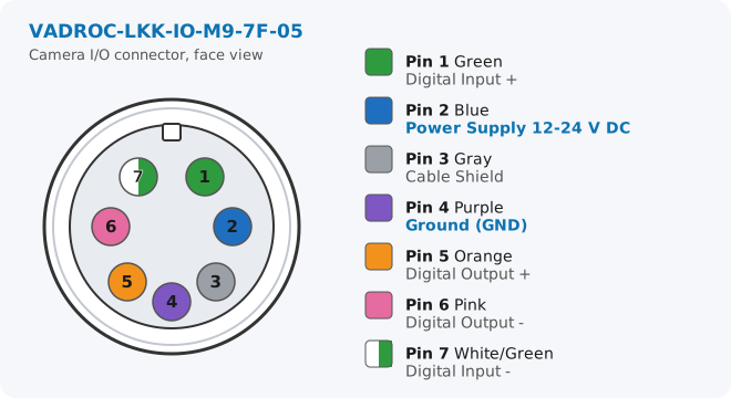
To power the camera, wire only the two power leads to your supply:
- Blue (Pin 2) ➜ positive terminal (+12-24 V DC)
- Purple (Pin 4) ➜ ground (GND, 0 V)
Connecting Gray (Pin 3, Cable Shield) to earth/chassis is recommended to improve noise immunity.
WARNING
Check the polarity before powering on. Reversing Blue and Purple, or applying more than 24 V DC, can permanently damage the camera.
Optional: digital I/O (hardware trigger)
Standard Pick[+] Flex setups trigger the camera over Ethernet (software trigger), so the digital I/O leads can be left unconnected. If your application needs hardware triggering or an output signal (for example a strobe), wire the relevant pins:
- Digital Input (trigger the camera): Green (Pin 1,
Digital Input +) and White/Green (Pin 7,Digital Input -) - Digital Output (camera status / strobe): Orange (Pin 5,
Digital Output +) and Pink (Pin 6,Digital Output -)
Refer to the camera datasheet for the input/output voltage ranges and wiring examples.
Network Configuration
After the physical connection, ensure the camera IP is correctly configured on the Server PC. See IP Configuration for the default camera addresses and how to change them. The camera IP must also match the value set in the Pick[+] Hardware Settings.
Robot Connection
In cases where the application will be controlled directly by the robot (instead of through a PLC):
-
Connect the Ethernet cable to the corresponding port on the Pick[+] Server PC.
-
Connect the other end of the Ethernet cable to the robot controller.
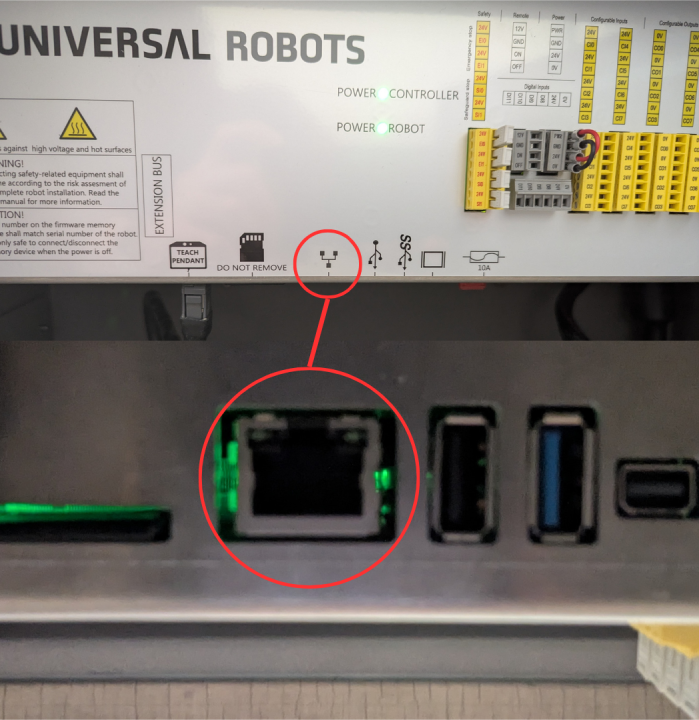
-
In your UR Teach Pendant, go to Settings → System → Network and configure network connection as follows:
- IP: 200.200.2.2
- Network mask: 255.255.255.0
- Gateway: 200.200.2.1 (Pick[+] server listens to robot on this IP)
Check UR Configuration for more information about Robot Connection issues