Collisions
The third step of the application wizard defines the physical elements whose geometry affects the pick. These are the tool mounted on the robot and, optionally, the scene that describes the workspace around it.
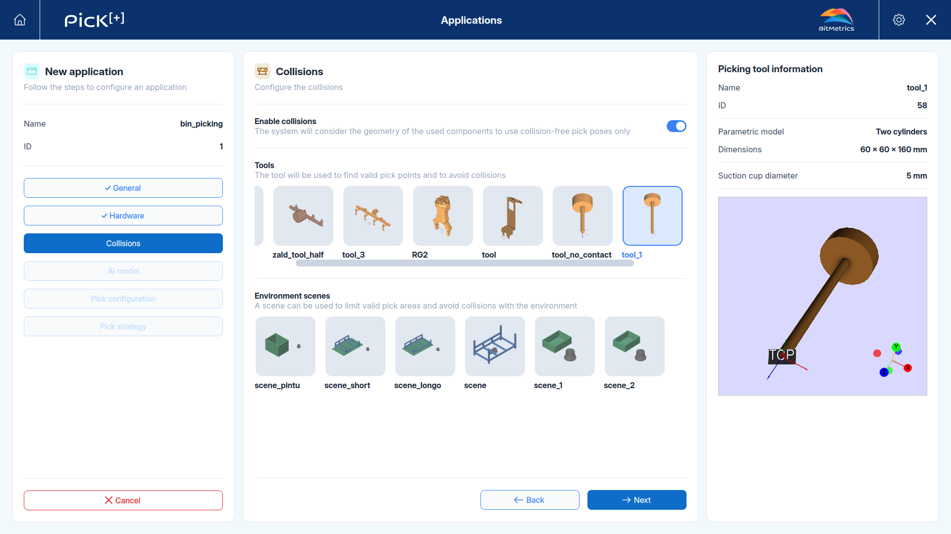
Enable Collisions
The Enable collisions toggle controls whether Pick[+] validates each pick candidate against the geometry of the selected components. With it ON, only collision-free pick poses are returned so any candidate whose tool would intersect the bin walls, the surrounding objects or the scene is discarded.
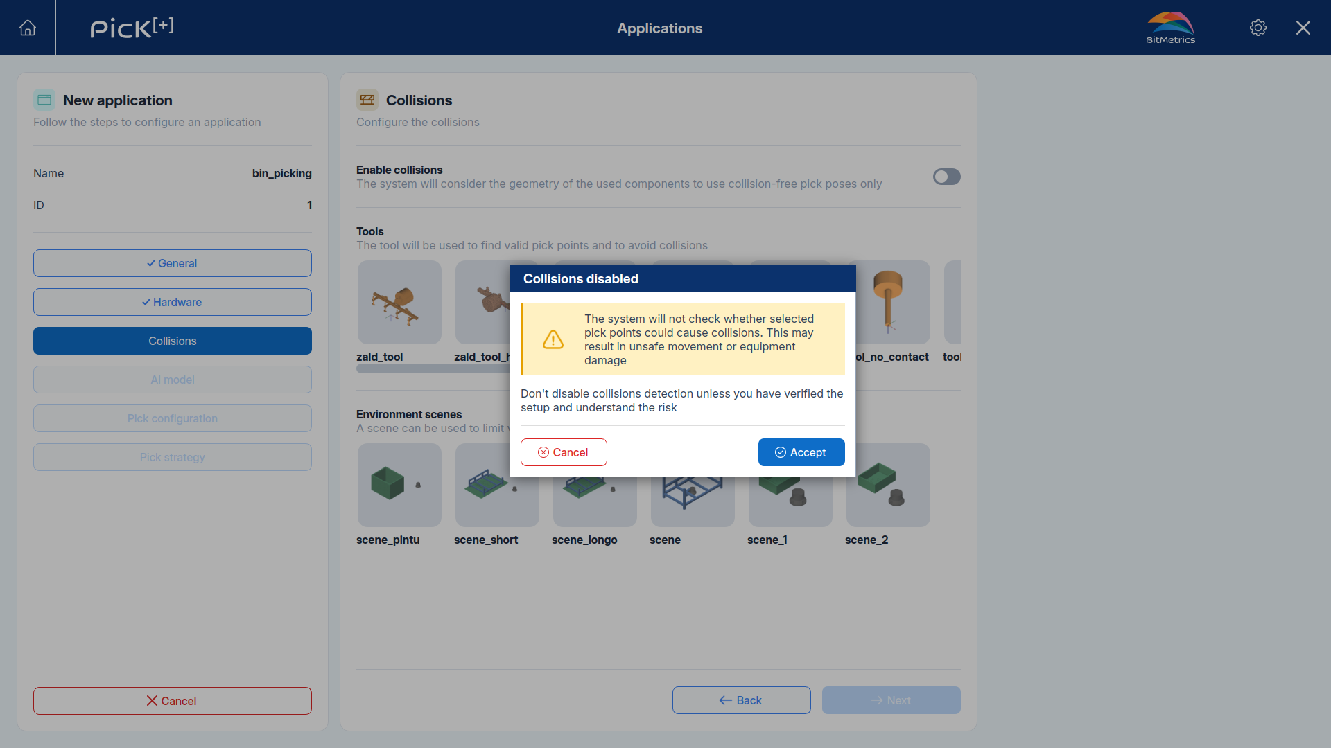
WARNING
With collisions disabled the system will not check whether selected pick points could cause collisions. This may result in unsafe movement or equipment damage. Only disable collision detection once the setup has been verified and the risk is understood.
Tools
The tool is the gripper or suction cup mounted on the robot flange. Pick[+] uses it for two things:
- To know the
TCPthat every returned pose refers to - To compute which grasps are physically feasible and collision-free.
Select one tool from the gallery. Selecting it opens the Picking tool information panel on the right:
| Parameter | Description |
|---|---|
| Name | The tool's name |
| ID | The tool's numeric identifier |
| Geometric model | The geometry used to approximate the tool for collision computation |
| Dimensions | The bounding dimensions of that parametric model in millimeters |
| Suction cup diameter | For vacuum tools, the diameter of the contact surface that has to rest on the object |
| Check contact | Whether every pick point is validated against the object surface, confirming that a flat region as wide as the suction cup diameter is available around it |
Auto-pick requires a vacuum tool
Auto-pick generates its grasps using the suction cup diameter. It scans the surface of each detected object looking for a flat region wide enough to fit that diameter, so that the whole contact surface rests on the part.
Any application that uses Auto-pick, either as its picking mode or as its alternative picking mode, must select a vacuum tool in this step.
Check contact extends that verification to the other modes
With Check contact enabled on the tool, the same verification of the flat region wide enough is applied to the points obtained by Mask center and Model alignment, a point whose surroundings are not flat enough for the whole suction cup to rest or without enough points in the 3D point cloud is discarded.
Environment Scenes
An environment scene describes the physical workspace. It contains the bins that hold the objects and the assets around them, each placed at its real position relative to the robot. Selecting one is optional, but it gives the application two capabilities:
- Pick area restriction: detections and pick points are filtered to the volume of the bins, so Pick[+] only searches where the objects actually are. See Selecting a bin in execution for how UR, ABB and a
PLCeach choose the bin. - Environment collision handling: the tables, structures and bin walls in the scene are taken into account when validating each candidate.
Selecting a scene opens the Scene information panel on the right:
| Parameter | Description |
|---|---|
| Name | The scene's name |
| Robot | The robot the scene was built for, since every element is positioned relative to its base |
| Number of items | How many bins and assets the scene contains |
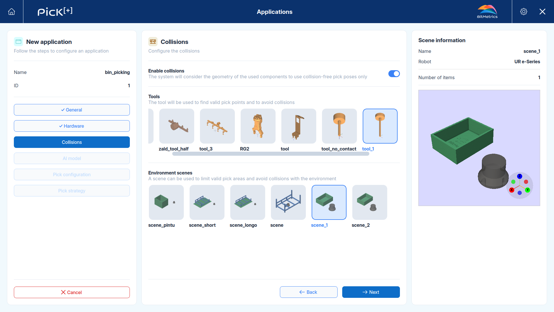
Scenes are built in Environment Scenes from the bins and assets libraries.
Selecting a bin in execution
A scene can contain several bins, and this step does not decide which one is used. That choice is made on every cycle by the robot program or the PLC, which is what allows a single application to empty different containers during the same routine.
Click Next to continue to the AI strategy.
What's Next?
-
AI Strategy
Choose how Pick[+] detects the objects and which AI model it uses.