Hardware
The second step of the application wizard defines the physical devices it runs on. These are the camera that captures the images, the device that triggers it and the devices that receive the computed pick poses.
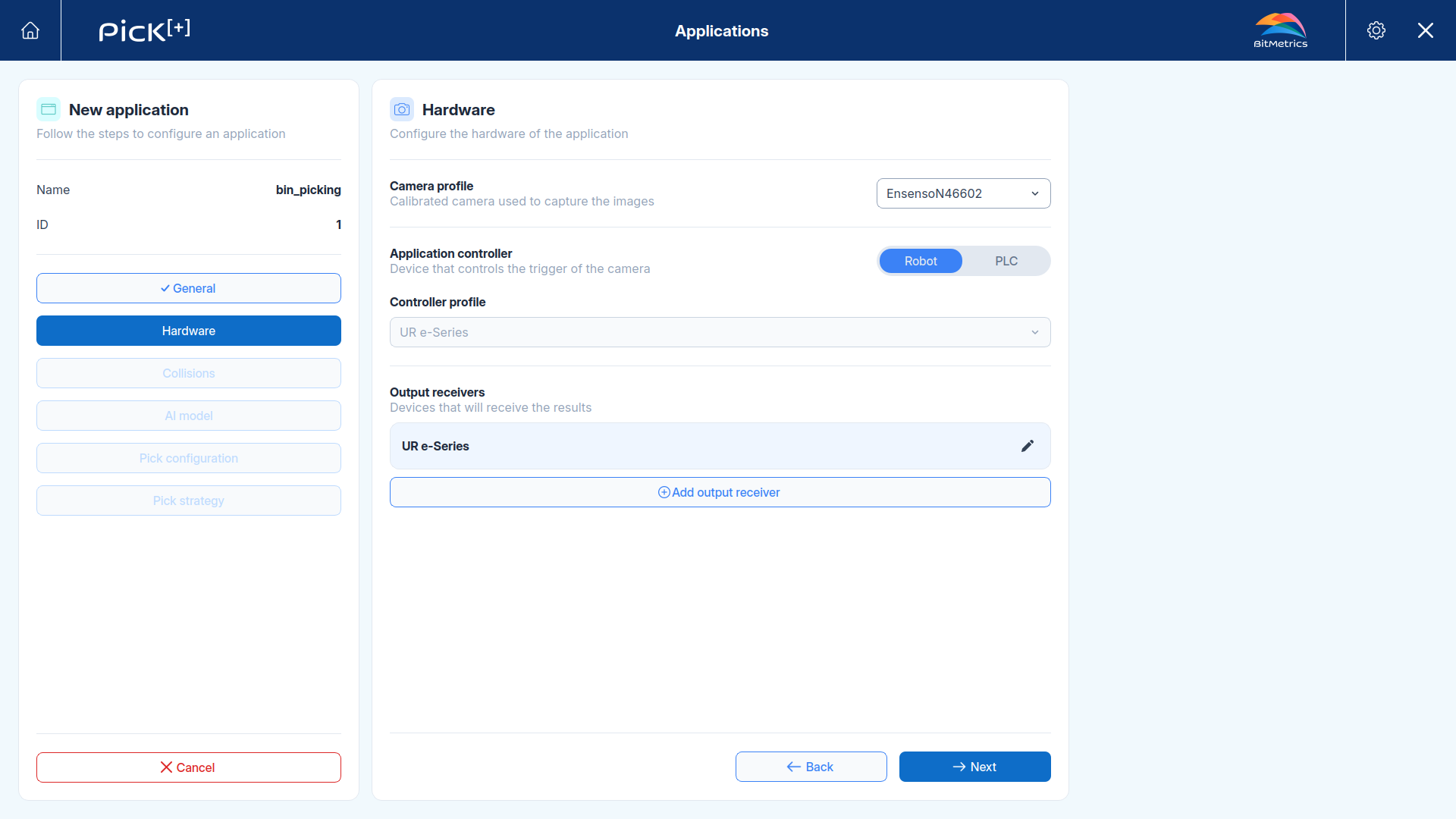
Every device in this step plays one of three roles, and the same device can play more than one. These are the roles shown as tags in the application summary:
| Role | Meaning |
|---|---|
Trigger |
The camera that captures the image |
Controller |
The device that orders the capture and starts the detection |
Receiver |
A device that reads back the resulting pick pose and its metadata |
In the most common setup a single robot is both controller and receiver, it asks for a capture and then reads the pose it has to move to.
Camera Profile
Select the calibrated camera that captures the images for this application. Only cameras with at least one completed calibration can be used. Once the camera is selected, the controller list below gets filtered.
Camera profiles
A camera profile holds the capture settings (exposure, image quality, capture type). Check Camera Profiles to learn how to created and tune them, and assign them in Hardware Settings.
Application Controller
The application controller is the device that controls the trigger of the camera, the one that decides when an image is captured and a detection starts.
Pick the controller type first and then its profile:
-
Robot: The robot program requests each capture. Use this when the robot drives the cycle, which is the standard setup for Universal Robots and ABB integrations.
-
PLC: A
PLCrequests each capture over Modbus TCP or Siemens S7. Use this when an external control system manages the cell. See PLC Application.
The Controller profile dropdown then lists only the profiles of that type that have been calibrated with the selected camera:
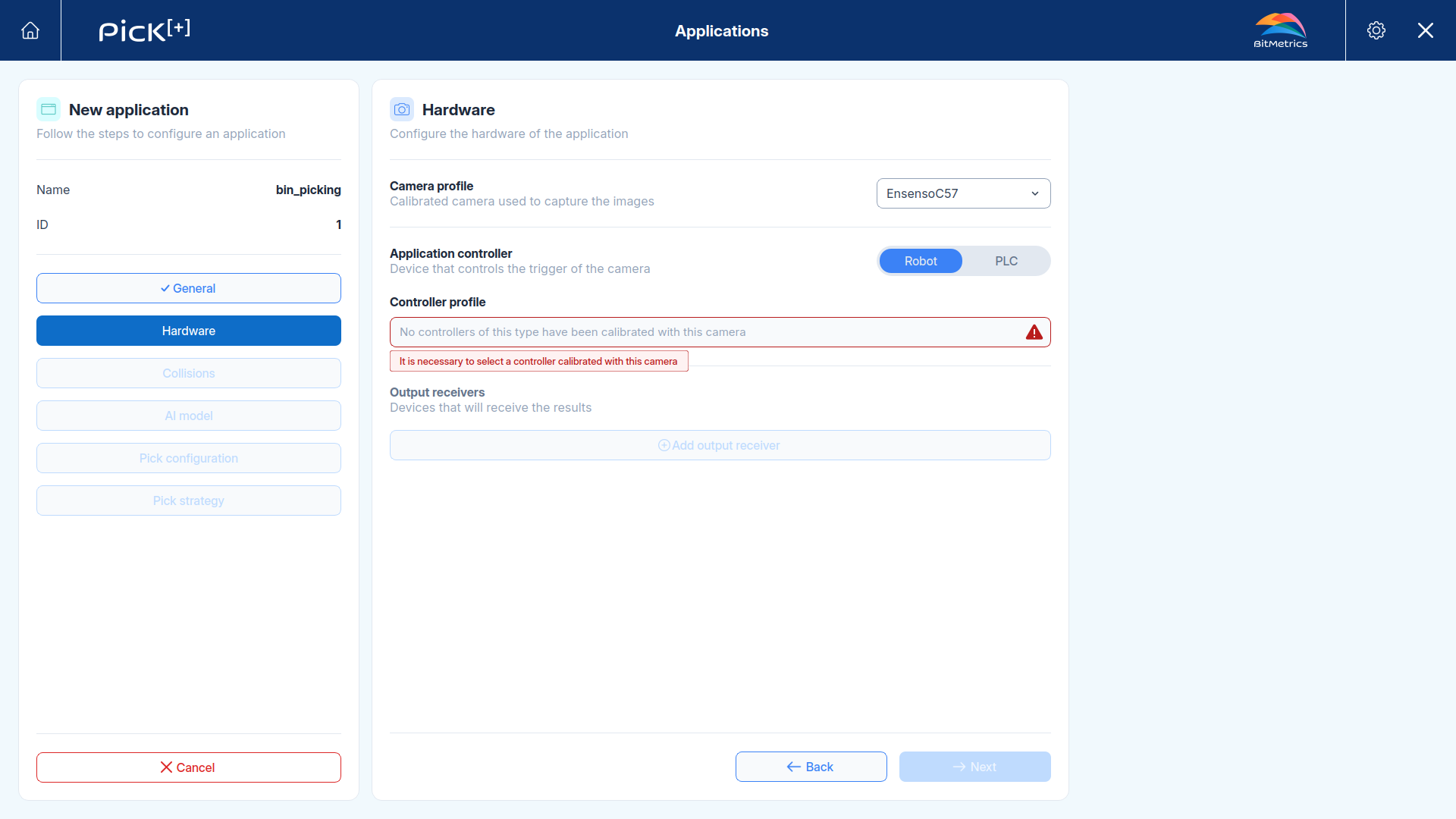
It is necessary to select a controller calibrated with this camera
This message means the camera and the controller you picked have never been calibrated together. Either choose a different camera, or run a new calibration for that camera and controller before continuing.
Output Receivers
Output receivers are the devices that receive the results of the detection like the selected pick pose and its metadata. Every application needs at least one.
Click Add output receiver to add an entry. Each entry has two fields:
| Field | Description |
|---|---|
| Output type | Robot or PLC |
| Profile | The specific device profile of that type |
Receivers are listed collapsed once configured. Click the icon to expand and edit one or the icon to remove it.
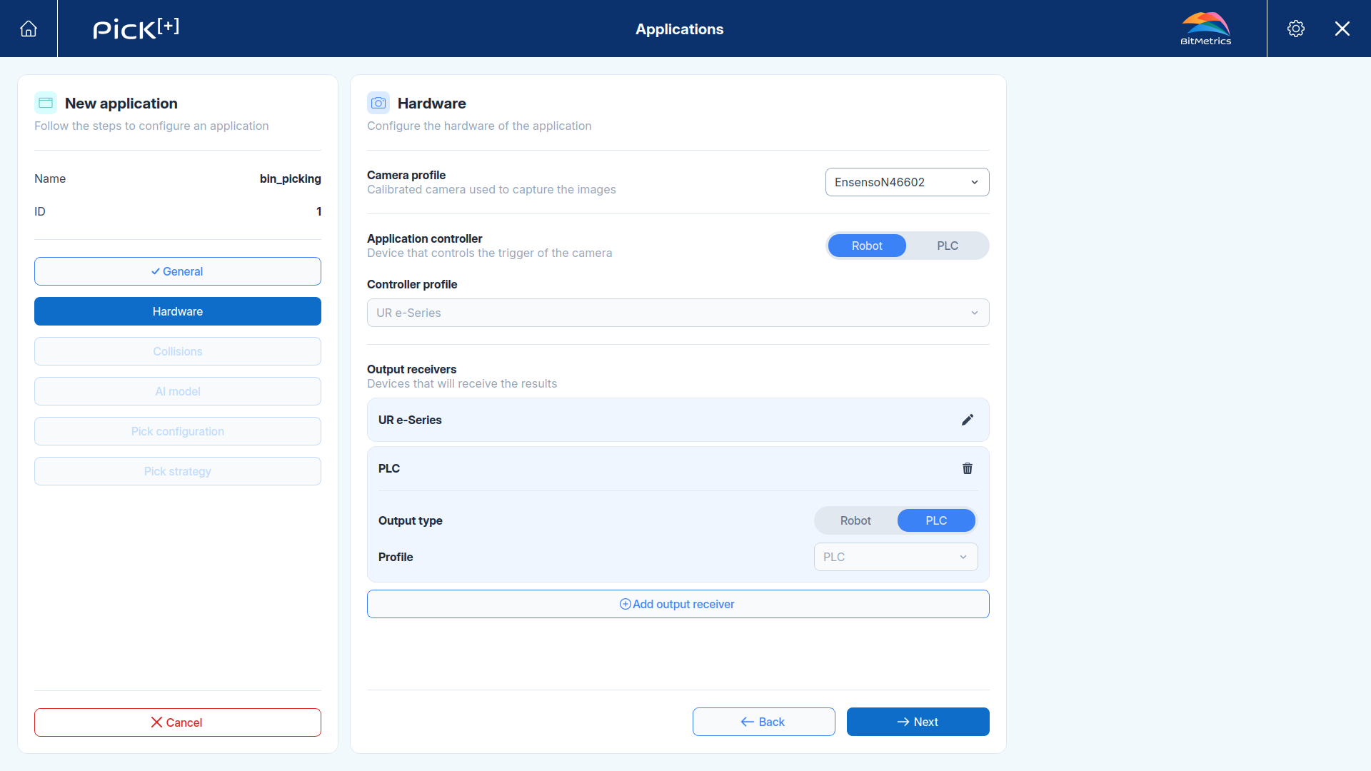
Adding more than one receiver is useful when several devices need the same result, for example a robot that performs the pick and a PLC that supervises the cell and logs the outcome. Each receiver reads the result through its own interface:
- A robot receiver reads it with
pick_plus_output(UR) orPP_Output(ABB). - A
PLCreceiver reads it through an output request.
Controller and receiver can be the same device
Selecting the same robot as controller and as output receiver is the normal single-robot setup. The robot triggers the capture and then reads back the pose it has to reach.
Click Next to continue to the collision configuration.
What's Next?
-
Collisions
Select the picking tool and the environment scene used to compute collision-free picks.